Summary
In this lab, we explored motors and building circuits using servo, DC and stepper motors. We used an Arduino to generate a pseudo-analog output voltage (PWM) to control a servo motor, and learned to drive DC and stepper motors using an H-Bridge.
Lab Objectives:
- Use PWM to drive a servo motor
- Use an H-bridge to drive a DC motor
- Drive a stepper motor with an H-bridge
Part 1
First part of lab used a servo motor controlled by a potentiometer. On this circuit, I decided to write the code for the functionality first. I expected it to be more difficult, but I found that it was fairly straight-forward and simple. I think the servo library made things much easier. I was able to closely follow the sample pseudo-code and quickly get it figured out.
#include <Servo.h>

Servo servo;  //Declare for servo

int value1 = 0;
int value2 = 0;
int pot = A0;

void setup() {
  Serial.begin(9600);
  servo.attach(3);  //Using pin 3
}

void loop() {
  value1 = analogRead(pot);
  value2 = map(value1, 0, 1023, 0, 179);

  servo.write(value2);  //Writes to servo motor


}

Part 2
In part 2, we moved on to a DC motor. The circuit powered the motor and caused it to spin clockwise, and a button press caused it to spin the other way. The button was the input, and the motor was the output. We used an H-Bridge to control the direction, which added an extra element of difficulty to the circuitry.

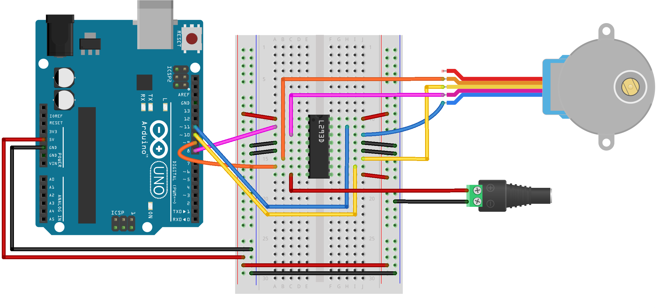
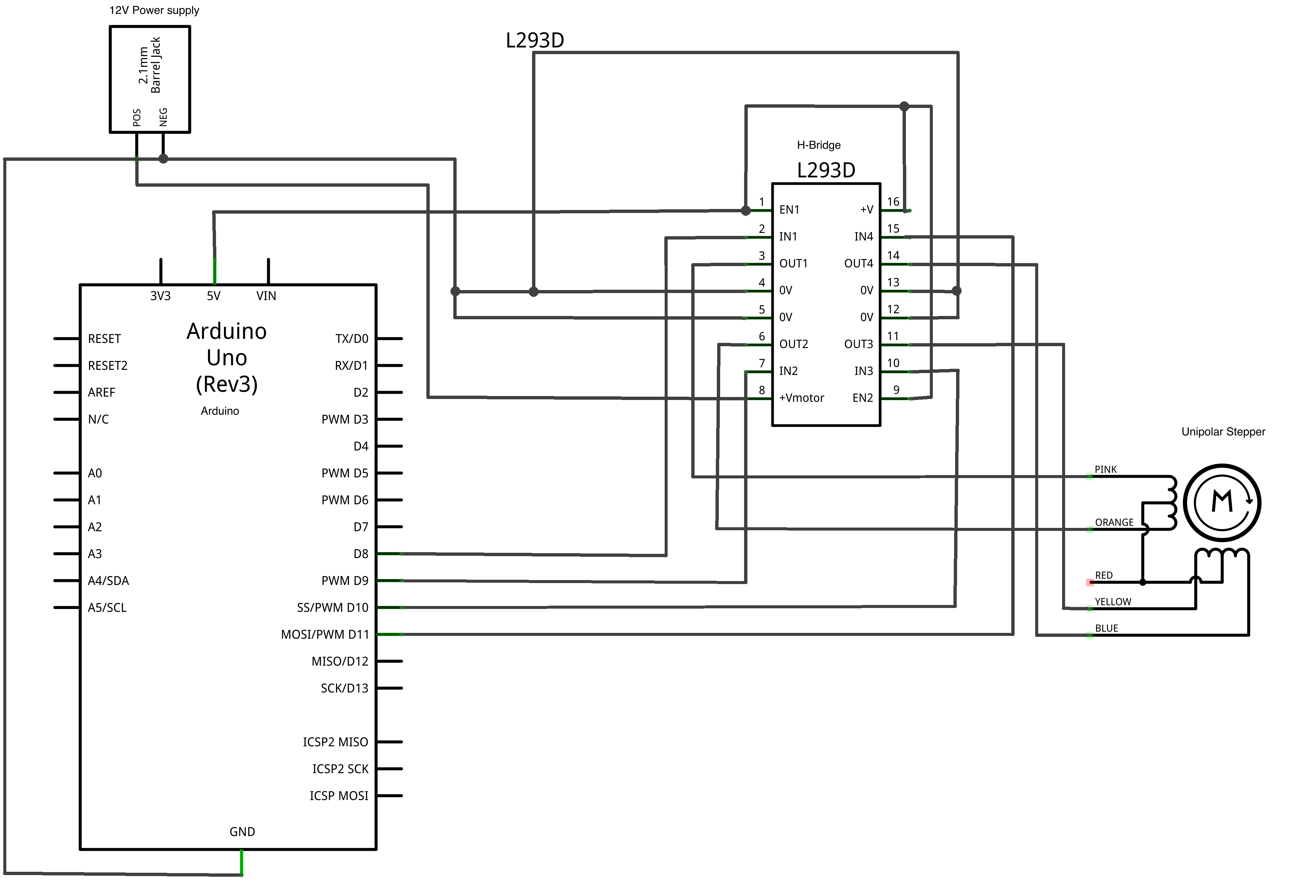
Part 3
Part 3 used a stepper motor. In my opinion, this was the most complicated part. Once again we used the H-bridge to control it. The code for this section wasn’t overwhelming, but this circuit took me the longest to connect. The schematic was a little intimidating, and I had to take some steps back a few times after making wrong connections. I eventually got everything in the right spot.